NFR22 Data Acquisition System (DAQ)
Data acquisition system on the 2021-22 Northwestern Formula Racing FSAE car (NFR22)
Details
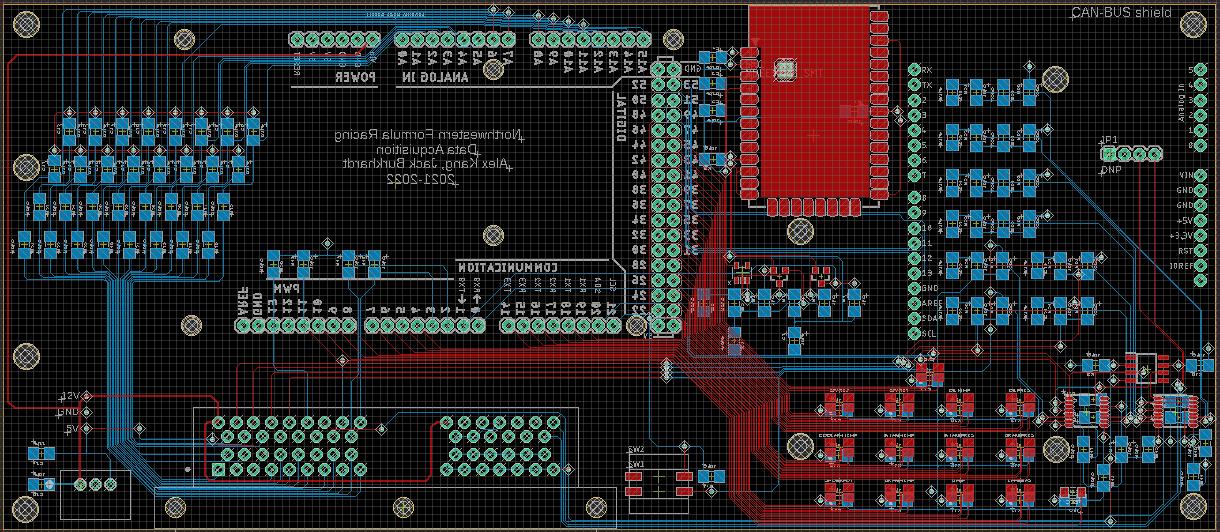
Originally, my job was to design, manufacture, test, and program the main data acquisition PCB on the car.
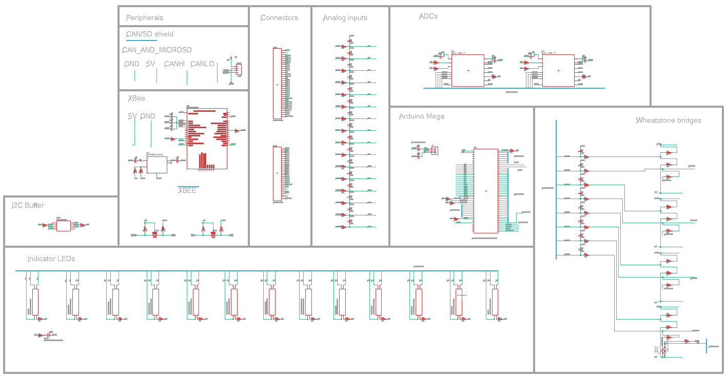
The main PCB had the roles of:
- Taking in data from various sensors spread around the car (total of 33 inputs).
- Converting raw sensor data to properly dimensionalized values that are human-understandable.
- Sending the processed data to the base station via telemetry.
After I got ahead of schedule, I also took on the task of two more boards:
- Intermediary daughter board:
- Added functionalities of IMU & GPS that NFR21 didn't have.
- Pitot tube breakout boards:
- 16 of these breakouts would be mounted to the car to measure fluid flow.
- Enables the aerodynamics subteam to make more informed design decisions.
Outcome
In the end, I reduced the main data acquisition PCB's size by 22% while keeping all functionality from NFR21.
Additionally, I implemented IMU, GPS, and pitot tube support to other boards that then outputted to the main board.
How to get it
The Autodesk EAGLE files (.brd, .sch) for all the boards can be found here.
Unfortunately, the Arduino code written to drive the boards has been lost and now only exists on the boards themselves.